Industrial 3d printing is changing how manufacturers design, test, and produce complex parts. Unlike conventional machining, it builds components layer by layer from a digital model. The process may use metal powder, polymer filament, resin, or composite material. A printer follows carefully prepared toolpaths, adding material until the part takes shape.
The workflow begins with computer-aided design and engineering analysis. Designers check wall thickness, support structures, heat behavior, and expected loads. The digital file then moves through slicing software, which converts geometry into thousands of thin layers. During production, sensors can monitor temperature, laser power, chamber conditions, and deposition speed. After printing, technicians may remove supports, clean surfaces, heat-treat metals, or machine critical dimensions. Inspection can include visual checks, coordinate measurement, computed tomography, or material testing. Small errors matter.
Industrial 3d printing is not simply a faster replacement for every factory process. It performs especially well with lightweight structures, customized tooling, replacement parts, and low-volume production. However, surface roughness, internal defects, material cost, and limited build volumes can affect the final result. Experienced teams validate designs through prototypes and documented process controls. They also compare printed parts with relevant ISO or ASTM guidance, supplier data, and customer requirements. Reliable production depends on qualified operators, traceable materials, calibrated equipment, and repeatable parameters. The results can disappoint. Even a successful print may need redesign. Understanding these practical limits makes the technology more credible, useful, and safer to apply across aerospace, healthcare, automotive, and industrial equipment manufacturing.
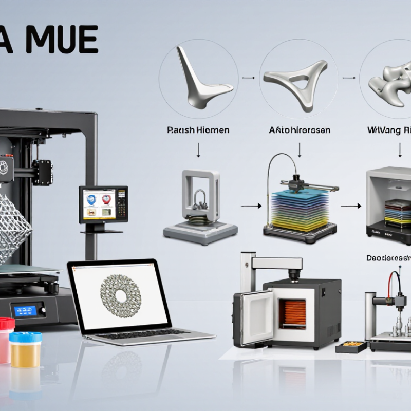
Industrial 3D printing builds physical parts directly from digital designs. Instead of cutting a shape from a solid block, a machine adds material layer by layer. This approach matters because it changes how factories develop, test, and produce components.
A digital model is sliced into thin cross-sections. The printer follows these paths with metal powder, polymer, resin, or another qualified material. Heat, light, or a binding agent joins each layer.
After printing, technicians may remove supports, clean surfaces, heat-treat parts, and inspect critical dimensions. In production settings, a small design change can become a test piece within days, rather than weeks.
This shorter loop helps engineers study airflow channels, lattice structures, and customized tools that conventional manufacturing may struggle to create.
The value is not simply speed. Industrial printing can reduce material waste, combine several components, and support production near the point of use. It can also help maintain older equipment when original parts are difficult to source.
Still, the process is not magic. Surface roughness, internal defects, material consistency, and costly post-processing can affect performance. Every serious application needs documented parameters and testing.
A printed part may look precise. It may not be reliable yet. Standards, operator training, and inspection data determine whether it belongs in a working machine. The technology keeps improving, but practical judgment remains essential.
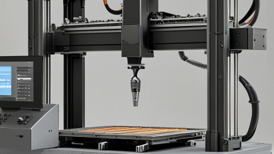
What Is Industrial 3D Printing and How Does It Work?
Industrial 3D printing builds parts layer by layer from a digital model. Unlike ordinary machining, it adds material only where the design requires it. The process begins with sliced geometry, carefully selected materials, and controlled machine settings. Temperature, layer thickness, and build speed can change the final result.
Powder bed fusion uses heat from a laser or electron beam to melt selected areas of a powder layer. It suits complex metal parts with internal channels and lightweight structures. Material extrusion pushes heated polymer through a narrow nozzle. This method is practical for fixtures, prototypes, and some production components. Vat photopolymerization cures liquid resin with light, producing fine details and smooth surfaces. However, some cured resins can be brittle or sensitive to heat.
Binder jetting deposits a liquid binder onto powder, then uses a separate curing or sintering stage. It can produce many parts efficiently, although shrinkage needs careful prediction. Directed energy deposition feeds metal powder or wire into a focused heat source. This technology works well for repairs, large components, and adding material to existing parts. Sheet lamination bonds thin layers into a solid form, but its material choices are more limited.
No technology is universally best. Each one balances strength, accuracy, speed, cost, and post-processing. In real workshops, support removal, powder handling, surface finishing, and inspection often decide whether a printed part succeeds. Design assumptions can also fail. A model that looks perfect on screen may warp, shrink, or require machining before use.
Industrial 3D printing creates parts layer by layer from a digital model. The process may extrude polymer, cure liquid resin, selectively fuse powder, or bind powder before post-processing.
The chart shows representative layer-thickness ranges commonly used in industrial systems. Smaller layers can improve surface detail, while larger layers can increase production speed. Actual results depend on material, machine configuration, part geometry, and process settings.
An industrial 3D print begins with a digital model created in CAD software. Engineers check wall thickness, holes, and load-bearing areas before exporting the file. Slicing software divides the model into hundreds of thin layers. It also sets the build direction, speed, temperature, and support structures. Small decisions matter here. A poor orientation can cause warping or weak joints.
The printer then builds the part layer by layer. In a powder-bed process, a recoater spreads a fine material layer across the platform. A laser or other energy source selectively fuses the required area. The platform lowers slightly, and a new layer covers the previous one. Other industrial systems deposit melted material or cure liquid resin with controlled light. Sensors monitor temperature, energy delivery, and movement during production. Operators still inspect the process because automated checks can miss unusual defects.
After printing, workers remove supports, excess powder, or uncured resin. Metal parts may receive heat treatment to reduce internal stress. Machining can improve critical holes and contact surfaces. Inspectors measure dimensions with gauges, scanners, or coordinate equipment. The first build is rarely perfect. I have seen minor distortion appear near sharp corners, even after careful planning. That result requires review, not guesswork. Engineers compare the part with the design, adjust parameters, and repeat the build when evidence demands it.
Industrial 3D printing builds parts layer by layer from a digital model. The process may use powder, resin, or metal wire. A machine selectively melts, cures, or deposits the material. According to the Wohlers Report 2024, the additive manufacturing industry reached about $20.0 billion in 2023, growing 13.5% year over year. That growth reflects real production demand, not only prototypes.
Material choice controls more than strength. Powder-bed metal systems suit heat-resistant components, while polymer systems can reduce weight and tooling costs. Engineers should check temperature, moisture, particle size, shrinkage, and recyclability before design approval. ASTM and ISO guidance also emphasizes process control, machine qualification, and traceable material records. Small details matter. A wet polymer can create pores, weak layers, and inconsistent dimensions.
Design requirements differ from conventional machining. Wall thickness, support structures, build orientation, thermal distortion, and powder removal must be considered early. Internal channels may be possible, but trapped powder can make them unusable. Production teams should define tolerances, inspection methods, surface-finish targets, and post-processing steps before printing. The 2024 Wohlers data also shows that professional services and production applications remain major parts of industry revenue, suggesting that printing alone is not the whole workflow. That point is easy to underestimate. In practice, failed builds often come from unclear specifications rather than the printer. Engineers should review designs with operators, test representative coupons, and revise assumptions after measurement. Reliability improves through evidence, although no design process is perfect.
| Technology | Working Principle | Typical Materials | Typical Layer Thickness | Key Design Requirements | Common Industrial Uses | Main Production Considerations |
|---|---|---|---|---|---|---|
| Material Extrusion FFF / FDM |
A heated nozzle deposits thermoplastic filament layer by layer until the component is formed. | ABS, PLA, nylon, polycarbonate, PEI, PPS, fiber-reinforced thermoplastics | Approximately 0.10–0.40 mm | Use support structures for overhangs; account for anisotropic strength, warping, shrinkage, and minimum wall thickness. | Functional prototypes, fixtures, jigs, low-volume tooling, ducts, and housings | Material drying, nozzle temperature, build-plate adhesion, chamber temperature, and post-processing affect quality. |
| Vat Photopolymerization SLA / DLP |
A liquid photopolymer resin is selectively cured with a light source, building the part in successive layers. | Standard, tough, flexible, high-temperature, castable, and biocompatible photopolymers | Approximately 0.025–0.15 mm | Orient parts to reduce peel forces; provide drainage holes for hollow sections; design adequate supports and avoid trapped resin. | Detailed prototypes, patterns, medical models, visualization models, and small precision components | Washing, support removal, and secondary UV curing are normally required; resin aging and moisture can affect consistency. |
| Powder Bed Fusion SLS |
A thermal source selectively fuses polymer powder, while surrounding unfused powder supports the part. | Nylon, polypropylene, thermoplastic elastomers, and glass- or mineral-filled polymers | Approximately 0.06–0.15 mm | Allow clearance between moving parts; consider powder removal routes, thermal shrinkage, and build orientation for dimensional stability. | Complex housings, ducts, lattice structures, customized products, and small production batches | No dedicated support structures are usually needed; powder refresh ratio, cooling time, depowdering, and surface finishing influence cost and quality. |
| Laser Powder Bed Fusion LPBF |
A laser selectively melts metal powder in a controlled atmosphere, creating a dense metal component layer by layer. | Stainless steel, aluminum alloys, titanium alloys, nickel alloys, and cobalt-chromium alloys | Approximately 0.02–0.06 mm | Use self-supporting angles where possible; add support structures for heat transfer and anchoring; avoid excessive overhangs and sharp thermal transitions. | Lightweight brackets, heat exchangers, conformal cooling tools, aerospace components, and medical implants | Powder handling, inert gas control, residual stress, heat treatment, support removal, machining, and inspection are important. |
| Electron Beam Powder Bed Fusion EB-PBF |
An electron beam selectively melts metal powder in a vacuum and fuses each layer to the previous one. | Titanium alloys, cobalt-chromium alloys, and selected high-temperature metal alloys | Approximately 0.05–0.10 mm | Plan for powder removal, reduced resolution compared with some laser systems, and orientation-dependent surface quality. | Porous structures, orthopedic components, and high-performance titanium parts | Vacuum operation, powder recycling, thermal control, surface finishing, and dimensional inspection affect production planning. |
| Binder Jetting | A liquid binder is selectively deposited onto a powder bed. The printed “green” part is subsequently cured, depowdered, and often sintered. | Stainless steel, tool steels, ceramics, sand, and selected metal powders | Approximately 0.05–0.10 mm | Compensate for sintering shrinkage; maintain uniform wall sections; include features that support handling of fragile green parts. | Batch production, sand molds and cores, decorative components, and selected metal parts | Sintering atmosphere, shrinkage control, powder packing, density variation, and post-sinter dimensional verification are critical. |
| Directed Energy Deposition DED |
Metal powder or wire is fed into a melt pool created by a laser, electron beam, or arc and deposited onto a substrate. | Titanium alloys, stainless steel, nickel alloys, aluminum alloys, and tool steels | Approximately 0.25–1.00 mm | Provide a suitable deposition path; allow machining stock; manage heat input, distortion, and access for the deposition head. | Repair, large metal structures, feature addition, coatings, and hybrid manufacturing | Surface finish is generally rougher than powder bed processes; machining, thermal treatment, and non-destructive inspection may be required. |
| Material Jetting | Small droplets of photopolymer or wax are selectively jetted and cured or solidified to form the part. | Photopolymers, waxes, and multi-material resin systems | Approximately 0.016–0.032 mm | Design for support removal; consider material compatibility, thin-wall behavior, and the limited long-term performance of some photopolymers. | High-detail visual models, multi-material prototypes, casting patterns, and presentation models | Support removal, UV exposure, material aging, cleaning, and color consistency influence final results. |
| Typical Digital Workflow | A 3D model is created or converted, checked, oriented, sliced, and transferred to the printer for layer-by-layer production. | CAD files, mesh files, build files, process parameters, and material records | Defined by the selected process and machine configuration | Verify watertight geometry, wall thickness, clearances, tolerances, overhangs, build volume, and inspection requirements before printing. | Rapid product development, customized production, tooling, spare parts, and distributed manufacturing | Traceability, repeatability, process validation, operator training, data security, and quality documentation become more important as volume increases. |
| Post-Processing and Quality Control | Printed parts are cleaned, cured, heat-treated, depowdered, machined, polished, coated, or inspected according to their application. | Process-specific consumables, machining tools, coatings, cleaning agents, and inspection equipment | Not applicable; finishing requirements depend on the final specification | Define critical dimensions, surface-finish targets, allowable defects, material certification, and inspection sampling before production. | Safety-critical parts, production tooling, certified components, and repeatable series production | Post-processing can represent a substantial share of total lead time and cost; inspection methods may include dimensional measurement, CT scanning, microscopy, or non-destructive testing. |
Note: Values are typical industrial ranges and vary according to machine configuration, material formulation, part geometry, process parameters, and post-processing.
Industrial 3D printing builds functional parts directly from digital models, usually layer by layer. The workflow begins with a computer-aided design file and carefully selected material. Software slices the model into thin sections. A machine then deposits, cures, or fuses each layer. After printing, technicians remove supports, finish surfaces, and inspect critical dimensions. Reliable production requires calibrated equipment, traceable materials, and documented quality checks.
Industrial applications include aerospace brackets, automotive tooling, medical fixtures, and customized production aids. Lightweight lattice structures can reduce material use and improve handling. Complex internal channels are also possible without traditional molds. Design teams can test several prototypes within days, rather than waiting weeks for specialized tooling. However, these advantages have limits. Printed parts may show uneven strength between layers. Heat, moisture, fatigue, and chemicals can also affect performance. Surface finishing may require machining, and large components can remain expensive. The technology is powerful, but it is not magic. A visually perfect part can still fail under repeated loads.
Tips: Define the required strength, temperature, and service life before choosing a process. Test prototypes under realistic conditions, including vibration and humidity. Check dimensions after finishing, not only after printing. Keep production records for every batch. Do not assume a successful prototype guarantees reliable mass production; workflow changes can alter results.