A Power Transformer Fuse is a small component with a demanding job: interrupting dangerous current while allowing normal energization and load changes. The choice affects protection, equipment damage, and service continuity. It cannot be made from voltage rating alone. Transformer capacity, primary voltage, expected fault current, inrush current, and downstream protection all matter.
The U.S. Department of Energy’s 2014 report, Large Power Transformers and the U.S. Electric Grid, described an aging transformer fleet, with an average age of about 40 years. That finding is a useful reminder: protection choices should consider the actual condition and operating history of the equipment, not just its nameplate. IEEE C37.48 provides application guidance for high-voltage fuses, including selection and coordination. In practice, engineers compare fuse curves with transformer damage limits and protective-device settings. A fuse that clears too slowly may leave a transformer exposed; one that operates during inrush can cause avoidable outages. Small details matter.
Common options include expulsion fuses, current-limiting fuses, and combination arrangements, each suited to different system conditions. Yet published curves do not capture every site detail. Cable length, ambient temperature, switching practices, and available fault current can change the result. That sounds tidy on paper. Field conditions rarely are. The sections ahead explain the main fuse types and a practical way to assess them. Use the manufacturer’s data and a qualified protection study before final selection.
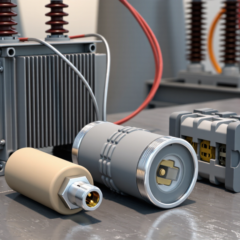
A primary-side fuse must survive normal load and magnetizing inrush, yet clear damaging faults before the transformer is harmed. Its interrupting rating must also exceed the available fault current at its installation point. IEEE Std C57.109-2018 provides through-fault withstand benchmarks by transformer category. For Category I units, the benchmark is 25 times rated current for two seconds. These are transformer withstand limits, not fuse settings. Not interchangeable. Fuse time-current curves must be checked against the transformer damage curve, inrush behavior, and downstream protection. IEEE Std C37.91-2021 offers application guidance for transformer protection and coordination.
Consider a 500 kVA transformer with a 4.16 kV primary and 5.75% impedance. Its primary full-load current is about 69 A; a simplified secondary-fault estimate is 69 ÷ 0.0575, or roughly 1,200 A referred to the primary. This screening calculation ignores source impedance and connection details. That shortcut is useful, but imperfect. A fuse that clears too quickly during inrush can cause nuisance outages; one that clears too slowly may expose windings to excessive thermal and mechanical stress. Compare actual manufacturer curves and fault studies before selecting a fuse.

Choosing a transformer fuse starts with the fault current, not just the transformer’s rated current. IEC 60282-1 covers high-voltage current-limiting fuses, while IEC 60282-2 covers expulsion fuses. The standards address different fuse designs and performance tests. They do not replace a site-specific protection study.
An expulsion fuse interrupts current by creating an arc inside a tube, then venting hot gases. It is often used outdoors, where clearance and exhaust direction can be managed.
A current-limiting fuse uses a sealed element to interrupt high fault currents quickly and reduce peak let-through energy. That can help protect equipment with limited short-circuit withstand.
But coordination matters. A fuse must tolerate transformer magnetizing inrush while still clearing damaging faults; its rating alone cannot confirm this. Check voltage, available fault current, transformer impedance, and coordination with upstream devices.
Real installations are messier than selection tables suggest. Cable length, ambient conditions, and enclosure details can change the outcome. Review the manufacturer’s time-current data and applicable IEC test information, then verify the choice against the complete protection scheme.
Shortcuts are risky.
To calculate transformer full-load current, use its kVA rating and rated voltage. For single-phase transformers, current in amperes equals kVA × 1,000 divided by voltage. For three-phase units, divide by voltage × 1.732. Use the line-to-line voltage for three-phase calculations.
For example, a 75 kVA, 480 V three-phase transformer carries about 90 A at full load. Small detail. Easy to miss.
That value is a starting point, not a fuse size. Fuse choice also depends on transformer inrush, conductor protection, fault levels, and coordination with upstream and downstream devices. Expulsion fuses and current-limiting fuses behave differently during faults; the right type depends on the installation and protection scheme. Check the transformer nameplate and manufacturer’s protection guidance, then have a qualified electrical professional verify the selection against applicable requirements. A calculation can be correct and still leave a protection gap.
When a power transformer is energized, magnetizing inrush can briefly reach 8–12 times rated current. The actual peak depends on switching instant, residual core magnetism, and system impedance. It is not a sustained overload. Still, a fuse chosen only from the transformer’s full-load current may melt during normal energization. A brief nuisance operation can interrupt service and complicate commissioning.
Check the fuse’s time-current curves against both the expected inrush profile and fault-clearing requirements. IEEE Std C37.91-2021, Guide for Protecting Power Transformers, addresses inrush as a key consideration in transformer protection coordination. Compare the fuse’s minimum-melting curve with the estimated inrush magnitude and duration, then verify coordination with upstream and downstream devices. Also account for ambient temperature and prior loading, which can affect fuse response. This step is easy to underestimate.
Tips: Use the transformer manufacturer’s inrush data when available. Confirm assumptions with the actual system voltage and switching conditions. If the curve gives little margin, review the selection with a qualified protection engineer; a larger fuse alone may weaken fault protection.
A transformer fuse must do more than open during a fault; it must interrupt safely at its installation point. Expulsion and current-limiting fuses behave differently, so compare their ratings and time-current curves, not just their ampere ratings. Start with available fault current, system voltage, transformer kVA, and primary-side fault duty. Small details matter. IEEE C37.48 provides application and coordination guidance for high-voltage fuses, but reliable selection depends on accurate system data.
Check that the fuse’s interrupting rating meets or exceeds the maximum available fault current at its location. Confirm that the ratings use compatible voltage and fault-current bases. Then compare time-current curves for the transformer fuse, upstream protection, and any downstream devices. The fuse should ride through transformer magnetizing inrush while clearing faults before the transformer’s damage limits are exceeded. Coordination is not always neat, especially when fault levels vary across operating conditions.
A practical study uses current system fault data, manufacturer curves, and the utility’s protection requirements. Check both minimum and maximum fault conditions; a fuse may coordinate well at one level and poorly at another. Field labels can also be stale. Verify fuse type and rating against the installed equipment before relying on them. Review the assumptions with a qualified protection engineer, and document any gaps rather than quietly guessing.
| Fuse Type | Typical Transformer Application | How It Interrupts Fault Current | Interrupting-Capacity Check | Coordination Considerations | Selection Guidance |
|---|---|---|---|---|---|
| Expulsion (vented) fuse | Overhead distribution transformers and installations where venting and the equipment configuration are suitable. | An arc is extinguished within the fuse tube; hot gases are expelled during operation. | Confirm the fuse’s rated interrupting current at the applicable system voltage is at least the maximum available fault current at its installation point. | Check the time-current curve against transformer inrush, allowable through-fault exposure, and upstream and downstream protective devices. Observe any manufacturer or installation limits on coordination. | Consider where a vented device is permitted and its available fault-current rating is adequate. Account for clearances, exhaust direction, and local installation requirements. |
| Backup current-limiting fuse | Often used with a series disconnecting device, such as a bayonet fuse, in a transformer primary circuit. | Limits and interrupts high fault currents within its specified operating range. It may not clear low-level overcurrents below its minimum breaking current. | Verify both the maximum interrupting rating and the specified minimum breaking current. The fuse must be applied within its rated voltage and operating range. | Coordinate the series device so it clears faults within the current range assigned to it, while the current-limiting fuse clears faults above that range. Check the combined assembly’s curves and ratings. | Use only when the complete series combination is suitable for the expected fault-current range. Do not assume the current-limiting element alone provides full-range protection. |
| Full-range current-limiting fuse | Transformer primary protection where the specific fuse is rated to interrupt the expected range, including low-level overcurrents. | Uses a current-limiting element to interrupt fault current; performance depends on the fuse’s tested ratings and application limits. | Check the rated interrupting current at the system voltage and confirm the fuse’s minimum breaking current is no greater than the lowest fault current it is required to clear. | Compare the full time-current characteristic with transformer inrush and damage limits, as well as relay, breaker, and secondary protective-device curves. | Choose only after confirming that its voltage, continuous-current, interrupting, and minimum-breaking ratings fit the installation and protection study. |
| Combination fuse arrangement | Transformer installations using two series devices to cover different portions of the fault-current range. | A low-current device typically handles lower overcurrents, while a current-limiting fuse handles higher fault currents; exact division is design-specific. | Check the ratings of each device and the tested or approved rating of the complete combination. Confirm the available fault current falls within the combination’s specified operating range. | Use the combination’s application data and time-current characteristics. Ensure there is no gap or overlap that compromises clearing, and verify transformer inrush ride-through. | Apply as a coordinated assembly, not as independently selected fuse links. Follow the equipment and fuse application instructions. |
| Bayonet (drawout) fuse | Commonly used as a transformer-mounted primary protective or disconnecting element, often in series with a backup current-limiting fuse. | The fusible element operates for faults within its specified range; it is not necessarily capable of interrupting the maximum available system fault current by itself. | Confirm its interrupting rating is adequate for the fault current it is assigned to clear, and check the rating of any series backup fuse and the combined arrangement. | Coordinate its curve with the backup fuse, transformer inrush, and upstream protection. Review the manufacturer’s stated crossover or coordination limits for the combination. | Do not infer high-fault capability from the fuse’s physical fit or continuous-current rating. Verify the complete protective scheme. |
| Transformer primary fuse selection checks | Applies to all fuse types and arrangements. | Fuse operation depends on its construction, rating, and the prospective current and voltage at the installation point. | Determine maximum available fault current from the system study. Compare it with the fuse interrupting rating at the applicable voltage; also check minimum breaking current where applicable. | Review time-current curves for transformer magnetizing inrush, load, transformer through-fault limits, and coordination with upstream and downstream devices. Include the applicable system voltage and grounding conditions. | Use IEEE C37.48 for guidance on application, operation, and coordination of high-voltage current-limiting and expulsion fuses. Confirm final selection against the applicable standard edition, equipment data, and local requirements. |
| Important: Interrupting capacity is not interchangeable with continuous-current rating. Ratings and coordination limits are specific to the fuse, voltage, and any series-device combination; verify them using the applicable product data and protection study. IEEE C37.48 provides application guidance and does not replace equipment ratings or a site-specific engineering review. | |||||